Architecture
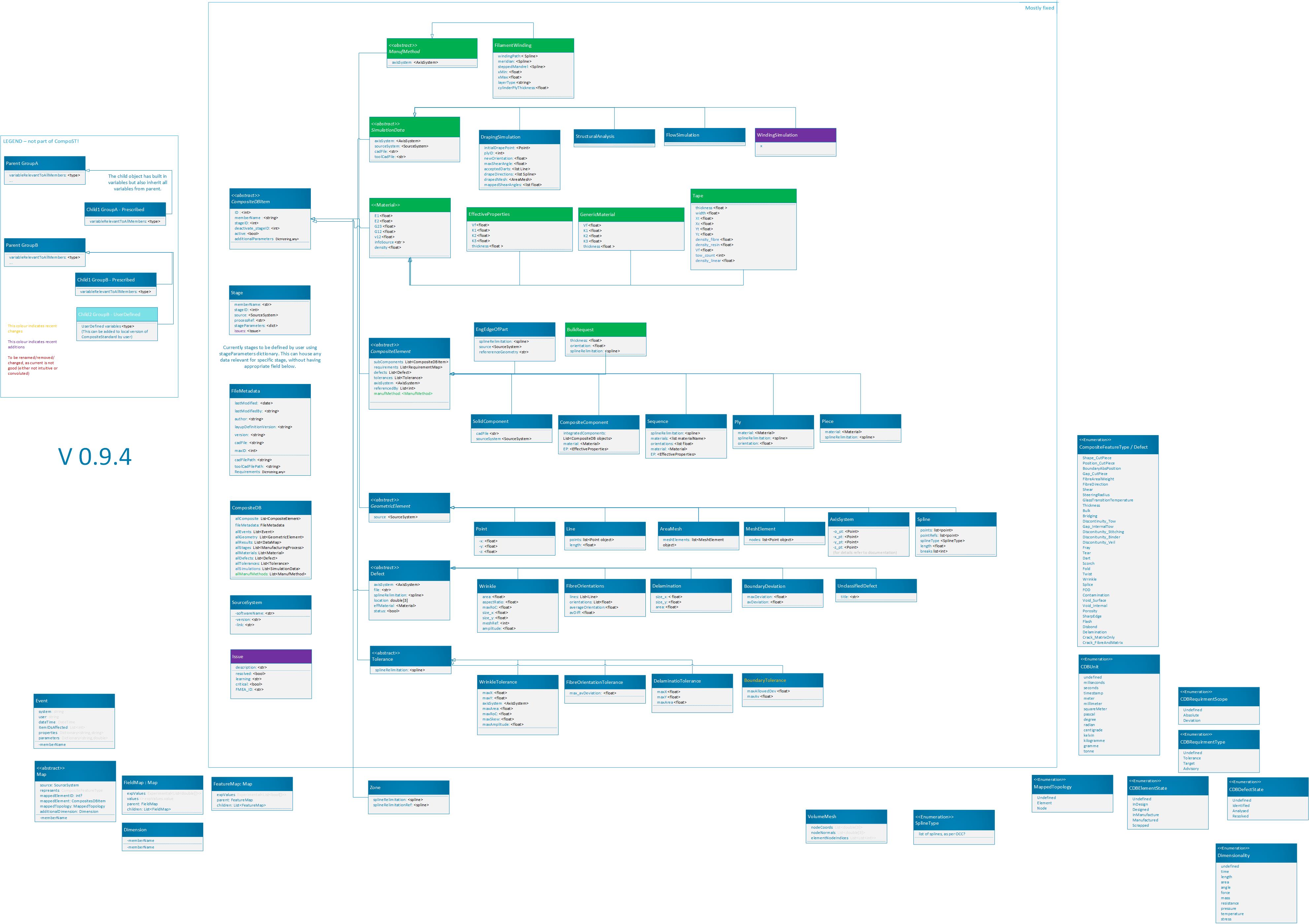
On the figure above, arrows point from an object 1 to object 2, where object 1 inherits from object 2.
The figure is also work-in-progress. The outline titled “mostly fixed” houses the objects that have been implemented and used. These will hopefully see only minor adjustments. Objects outside this area might end up being standardised differently than currently suggested.
All fields are optional unless otherwise specified, or unless required to construct specific object.
Where the same attribute is being called in parent and child (e.g. axis being referenced in ply, and in some of corresponding cut pieces), the more detailed (child) component supersedes the corresponding parent definition.
CompositeDB object is the main object of the Composite Standard. All objects are stored in lists named all***.
Object definitions
- CompositeStandard.CompositeDB(BaseModel)
All elements and all geometry are all stored here and used elsewhere as refrence Points are stored withing those, as referencing is not efficient
BaseModel input signifies the default generation with Pydantic library, without any local parent.
- Parameters:
name – str - name
allComposite – list - List of CompositeElement type objects
allEvents – list - List of “events” objects - all = exhaustive list
allGeometry – list - List of “GeometricElement” objects - all = exhaustive list
allStages – list - List of “Stages”, all stages where CompoST file is edited (manufacturing, NDT, simulation…)
allMaterials – list - List of “Material” objects - all = exhaustive list
allDefects – list - List of “Defect” objects - should contain all, that are referenced elsewhere
allTolerance – list - List of “Tolerance” objects
fileMetadata – ‘FileMetadata’ - metadata for this CompoST file
allSimulations – list - List of “SimulationData” objects
allManufMethods – list - List of “ManufMethod” objects
- CompositeStandard.FileMetadata(BaseModel)
Metadata related to this particular part.
- Parameters:
lastModified – date
lastModifiedBy – str - latest changes to the file have been done by
author – str - initial part definition created by
version – str - version of the CompoST used to work with this file
layupDefinitionVersion – str - initial part layup definition generated by
cadFile – str - related CAD file, if references to geometries are required, .step format is recommended. Should be stored in same folder.
toolCadFilePath – str - only used if tool has separate CAD file from the above
maxID – int - maxium ID used for any object int the file, used for preventing duplicaiton of IDs
cadFilepath – str - should only be used when CAD could not be stored in same folder as this file
Requirements – dict - bespoke dictionary of requirements that user wants stored for later use or reference. It might be useful to create template for this for type of product e.g. Pressure Vessel. However, this standardisation is beyoned the scope of CompoST.
- CompositeStandard.CompositeDBItem(BaseModel)
- Parameters:
memberName – str - name
additionalParameters – dict - to hold use-case specific values (to be further defined). This should never hold copies of IDed objects, as these cannot be re-linked on deserialization. If reference to objects elsewhere in CompoST are required, ID reference should be used, not full object.
stageIDs – int - reference to Stage object
deactivate_stageID – int - this object is not relevant after this stage, either it has been superceeded or it’s purpose was fullfilled
active – boolean - on default “True”, can be turned “False” to indicate this is no longer representative of up-to-date part
ID – int - used for references between objects
One extra parameter can be passed to all objects that inherit from CompositeDBItem. The mainCompoST parameter is not stored, not serialized, but is used to automatically add ID and iterate the maxID within mainCompoST.
- Parameters:
mainCompoST – CompositeDB - main database this object belongs to. This is not stored, only temporarily used to assign and iterate IDs.
- CompositeStandard.SimulationData(CompositeDBItem)
This is abstract class, parent for various types of simulations.
- Parameters:
axisSystem – ‘AxisSystem’ - reference to axis system
sourceSystem – SourceSystem - the software or tool used for analysis
cadFile – str - path and name to CAD file
toolCadFile – str - path and name to CAD file for tool (if different)
- CompositeStandard.GeometricElement(CompositeDBItem)
- Parameters:
source – str - the software, script, or database that this object originated from
refFile – str - reference full name of dedicated file housing this geometry (assume same directory)
- CompositeStandard.CompositeElement(CompositeDBItem)
This includes any object that is used to describe composite component specifically.
- Parameters:
subComponent – list -
get(), either as object or IDrequirements – list - list of objects of Requirement type, to be further specified
defects – list - list of “defects” type objects
tolerances – list - list of “tolerance type objects
axisSystem – ‘AxisSystem’ - refernce axis system object in allGeometry
referencedBy – list - optional list of objects that currently reference this object
manufMethod – ManufMethod - manufacturing method object
- CompositeStandard.Point(GeometricElement)
- Parameters:
x – float
y – float
z – float
- CompositeStandard.Line(GeometricElement)
- Parameters:
points – list - list of two points , no more - no less
length – float - can be calculated from above, but can be stored to prevent calculation duplication
- CompositeStandard.AxisSystem(GeometricElement)
The three vectors listed bewow must be perpendicular to each other.
- Parameters:
o_pt – CompositeStandard.Point - origin location of axis system expressed in global axis system
x_pt – CompositeStandard.Point - point, (x_pt-o_pt) denoting x-vector of new axis system
y_pt – CompositeStandard.Point - point, (y_pt-o_pt) denoting y-vector of new axis system
z_pt – CompositeStandard.Point - point, (z_pt-o_pt) denoting z-vector of new axis system (this one is auto-calculated)
There were 3 main core requirements for definition of Axis System. It should be possible to write out reasonably simple axis system by user, without any calculations. Minimum number of values should be used for initial full definition of the axis system (8). The perpendicularity of the 3 axis should be enforeced without user participation.
The class definition automatically calculates z_pt, when this object is initialized or altered.
If y_pt made axis is not perpendicular to x_pt made axis, y_pt is recalculated using z_pt. User is encouraged to specify first 2 axis perpendicular to each other. However, if user fails to do so the object adjusts itself (at least when using the standard CompoST library in Python).
User cannot set z_pt on it’s own. Upon any changes this is recalculated from x_pt, y_pt and o_pt.
- CompositeStandard.Material(CompositeDBItem)
Abstract class housing different types of materials. For generic material, where these properties are used use GenericMaterial that uses this class as a parent.
User of the format is responsible for using consistent units. CompoST does not enforce units used.
- Parameters:
E1 – float - young’s modulus in primary direction
E2 – float - young’s modulus in secondary direction (in-plane)
G23 – float - shear modulus
G12 – float - interlaminar shear modulus
G13 – float - shear modulus
v12 – float - poisson ratio in plane
v13 – float - poisson ratio out-of-plane in principle direction
v23 – gloat - poisson ratio out-of-plane in transverse direction
infoSource – str - reference to source of the information
density – float
conductivity – float
failureCriteria –
CompositeStandard.FailureCriteria- specialized failure criteria objecta1 – float - thermal expansion in principle direction
a2 – float - thermal expansion in transverse direction
a3 – float - thermal expansion in out-of-plane direction
- CompositeStandard.GenericMaterial(Material)
Default material class, if no pre-defined material class fits better.
- Parameters:
K1 – float - permeability in primary direction
K2 – float - permeability in secondary direction (in-plane)
K3 – float - permeability out of plane / through thickness
thickness – float - out of plane thickness
Vf – float - volume fraction
- CompositeStandard.EffectiveProperties(CompositeDBItem)
Effective material properties. Usually calculated properties for laminate, but also may be used for defect knockdown properties etc.
- Parameters:
K1 – float - permeability in primary direction
K2 – float - permeability in secondary direction (in-plane)
K3 – float - permeability out of plane / through thickness
thickness – float - out of plane thickness
Vf – float - volume fraction
- CompositeStandard.Piece(CompositeElement)
In practical terms this is section of ply layed-up in one (particulartly relevant for AFP or similar)
- Parameters:
splineRelimitaion – ‘Spline’ - points collected as spline for relimitation
material – ‘Material’ - reference ‘Material’ object
- CompositeStandard.Ply(CompositeElement)
- Parameters:
splineRelimitaion – ‘Spline’ - points collected as spline for relimitation
material – ‘Material’ - reference ‘Material’ object
orientation – float - direction of lay-up with reference to x-axis of placementRosette
- CompositeStandard.Sequence(CompositeElement)
Can either be defined complely by inherited properties (ply list in subComponents).
Or can be defined by list of orientations and materials, if no additional information is required.
For single-material laminate leave “materials” empty, and fill in “singleMaterial”
The subComponents in sequence must be ordered tool placement (first object is initial ply placed on the tool)
- Parameters:
orientations – list - list of floats, orientations listed with reference to placementRosette
materials – list - list of ‘Material’ objects
material – ‘Material’ - reference ‘Material’ object
splineRelimitaion – ‘Spline’ - points collected as spline for relimitation
EP – ‘EffectiveProperties’ - effective properties for the entire sequence
- EngEdgeOfPart(CompositeElement)
- Stands for engineering edge of part.
- Parameters:
splineRelimitaion – ‘Spline’ - points collected as spline for relimitation
source – ‘SourceSystem’ - CAD system where this was defined
referenceGeometry – str - the name of edge of part defining geometry, as used inside CAD system
- CompositeStandard.CompositeComponent(CompositeElement)
- Parameters:
integratedComponents – list - allows for integrating othre complete CompoST databases as sub-components
ED – ‘EffectivePropertie’ - Effective properties are only specified when applicable for the complete ‘CompositeComponent’, if different from ‘material’
material – ‘Material’ - reference ‘Material’ object
- CompositeStandard.SourceSystem(BaseModel)
- Parameters:
softwareName – str
version – str - version used to generate objects referencing this
link – str - link to GitHub, docs… where appropriate
- CompositeStandard.MeshElement(GeometricElement)
- Parameters:
nodes – list - Point objects
- CompositeStandard.Spline(GeometricElement)
- Parameters:
splineType – int - types of splines based on OCC line types (ref to be provided)
pointRefs – list - list of IDs (only use this variable if ‘points’ variable unused
points – Point - This variable prevents complex ID referencing for points that belong to this spline only
length – float - calculated lenght of spline
breaks – list - list of integers referencing points which break spline into multiple for visual representation (e.g. sharp corners), this refers to points if available, or pointRefs.
- CompositeStandard.Defect(CompositeDBItem)
Storing a defect belonging to this class only stores the data regarding the feature. Weather or not this classifies as a defect in enginering process, depends on comparing the data stored here with the appropriate
CompositeStandard.Tolerance()- Parameters:
status – bool - None = not evaluated, True = defect outside of tolerance, False = deviation but fits within tolerance
location – float - x,y,z location
effMaterial – EffectiveProperties - adjusted material class saved
axisSystem – ‘AxisSystem’ - reference to AxisSystem object
file – str - reference to file which houses defect - not needed if relimitation defined directly in CompoST
splineRelimitation – Spline - object defining the area in question. If neither of spline definitions is used, it should be assumed the defect applies to full part as provided in CAD.
- CompositeStandard.Wrinkle(Defect)
- Parameters:
area – float - can be calculated in various more precise ways, but in general this can be approximated by size_x*size_y
aspectRatio – float - typically size_x/size_y
maxRoC – float - machimum “rate of changes” (RoC), or slope, is the angle of deviation towards the apex, in simplest case of wrinkle in x direction it can be approximated by: [ RoC = arctan(maxAmplitude/(0.5*maxX)) ]. In Radians.
size_x – float - maximum size of the deviation in x direction of the relavant axis system
size_y – float - maximum size of the deviation in y direction of the relavant axis system
meshRef – int - mesh corresponding to defect area or volume
amplitude – float - the size of the defect in out-of plane direction
- CompositeStandard.SolidComponent(CompositeElement)
CAD shapes, for instace useful when using a 3D core/insert
- Parameters:
cadFile – str - file path to the part, or reference to PLM site
sourceSystem – SourceSystem - the software used to generate 3D shape
location – str - relative or full path to the 3D file (bespoke local references, for instance for use in PLM, can be used here)
- CompositeStandard.Tolerance(CompositeDBItem)
- Parameters:
splineRelimitation – Spline - object defining the area in question
- CompositeStandard.WrinkleTolerance(Tolerance)
- Parameters:
maxX – float - maximum size of the deviation in x direction of the relavant axis system
maxY – float - maximum size of the deviation in y direction of the relavant axis system
axisSystem – ‘AxisSystem’ - axis system reference
maxArea – float - can be calculated in various more precise ways, but in general this can be approximated by maxX*maxY
maxRoC – float - Rate of change (RoC), or slope, is the angle of deviation towards the apex, in simplest case of wrinkle in x direction it can be approximated by: [ RoC = arctan(maxAmplitude/(0.5*maxX)) ]. In Radians.
maxSkew – float - [definition to be croudsourced later]
maxAmplitude – float - maximum out of plane deviation
- CompositeStandard.FibreOrientations(Defect)
- Parameters:
lines – list - list of Line objects, as scanned and translated into points and vectors
orientations – list - list of floats that should be the same size as
lines. This could also be calculated fromlinesandaxisSystem.avDeviation – float - average of local differences between orientation and defined ply orientation. This is more indicative than ‘averageOrientation’ as that one can offer falsely optimistic results.
averageOrientation – float - average of the above. This average does not take into account lenght of the lines, but simply averages all data points as if they were equal.
- CompositeStandard.Tape(Material)
- Parameters:
thickness – float - out of plane size
width – float - width of tape
density_fibre – float - density of the fibres
density_resin – float - density of the resin
Vf – float - volume fraction
tow_count – int - number of tows in tape
density_linear – float - typically g/m density of individual fibre
- CompositeStandard.FailureCriteria(BaseModel)
- Parameters:
Xt – float - Tensile strenght in principle direction
Yt – float - Tensile strenght in transverse direction
Xc – float - Compressive strenght in principle direction
Yc – float - Compressive strenght in transverse direction :param tau: float - shear strength
The objects below are temporary definitions, that might still be subject to changes. Included for testing purposes.
- CompositeStandard.FibreOrientationTolerance(Tolerance)
- Parameters:
max_avDeviation: – float - average difference to intended ply orientation based off all sampling points within relimitation
- CompositeStandard.DrapingSimulation(SimulationData)
- Parameters:
initialDrapePoint – point - location of first intended contact between ply and tool
plyID – int - ply ID, one DrapingSimulation object for each ply - if z=0 it likely needs a projection to surface in z vector
newOrientation – float - Prescribed orientation of ply at the initial draping location
maxShearAngle – float - maximum predicted shear angle in the full ply
acceptedDarts – list of Line objects - list of lines indicating accepted locations for darts
drapeDirections – list of Spline objects - list of splines indicating draping directions, only one spline is to be provided in the list if only initial draping direction matters
drapeMesh – AreaMesh - this mesh object corresponds to drapped ply, and is used for mapping shear angles
mappedShearAngles – list of floats - list of shear angles ordered according to elements in drapeMesh
- CompositeStandard.Stage(BaseModel)
Stage can be used as standalone object that is related to an actual process (NDT/Manufacturing/Analysis…). More details about the intended purpose of stages are available in Stages.
- Parameters:
stageID – int - unique stage identifier
memberName – str
source – SourceSystem
processRef – str - This is used to reference a file which describes process in question. CompoST is part focused, so processes are only referened here, rather than process details being stored.
stageParameters – dict - This dictionary allows for bespoke definitions of extra stage parameters, by the user.
- CompositeStandard.Zone(CompositeDBItem)
There are many potentially uses of Zones, but for now author refrains from fully defining this, until Zones figure in multiple use-cases.
- Parameters:
splineRelimitation – Spline - object defining the area in question
splineRelimitationRef – int - same as above but refenced as
IDonly.
- CompositeStandard.Delamination(Defect)
Delamination occurs between two layers/plies, the convention is to append it to the one that is in the tool direction.
- Parameters:
size_x – float - length in x axis direction
size_y – float - length in y axis direction
area – float
- CompositeStandar.UnclassifiedDefect(Defect)
This class is to be used when the defect you are storing about does not have dedicated class
- Parameters:
title – str - this is to be used to assgin classification to the defect
- CompositeStandard.DelaminationTolerance(Tolerance)
- Parameters:
maxX – float - maximum length in x axis direction
maxY – float - maximum length in y axis direction
maxArea – flaot - maximume allowed area per defect
- CompositeStandard.BoundaryDeviation(Defect)
This defect is generated by comparing initial definition of boundary (of layer/sequence/piece/…) to boundary measured in later “Stage”.
- Parameters:
maxDeviation – float - maximum distance of a measured point from intended boundary
avDeviation – float - average deviation along the boundary
- CompositeStandard.BoundaryTolerance(Tolerance)
- Parameters:
maxAllowedDev – float - maximum allowed distance of a measured point from intended boundary
maxAv – float - maximum allowed average deviation along the entire boundary
- CompositeStandard.ManufMethod(CompositeDBItem)
- Parameters:
axisSystem – ‘AxisSystem’ - axis system reference
- CompositeStandard.FilamentWinding(ManufMethod)
- Parameters:
windingPath – ‘Spline’ - Spline defined path of material, as wound on the mandrel
meridian – ‘Spline’ - 2D cross section of PV (assumes axisymmetry) - if this shape is revolved it should produce the PV shape.
steppedMandrel – ‘Spline’ - for first ply this is equivalent to meridian, then stepped mandrel defines the outermost shape including built-up material
xMin – float - relevant for hoop layers, defines start point for winding (minimum x-direction limit)
xMax – float - relevant for hoop layers, defines start point for winding (maximum x-direction limit)
layerType – str - hoop/helical-geodesic/helical-nongeodesic TODO make this into prescribed keywords and force selection of those only
cylinderPlyThickness – float - Ply thickness in the cylinder area
- CompositeStandard.BulkRequest(CompositeElement)
This class is used when certain thickness of certain orientation is required, but it has not yet been turned into individual layers. When this object is active, it remains to be split into manufacturable layers. It should be deactivated when individual layers have been defined.
- Parameters:
thickness – float - intended thickness in this orientation
orientation – float - orientation
splineRelimitation – ‘Spline’ - this is specified only if the delmitation is already known for all the resulting layers