Logic and philosophy
Assembly Order
The objects are ordered from tool surface, as they appear in the AllComposite list within CompositeStandard.CompositeDB(). This is the most practical way to structure composite object for most approaches. It might require additional operations when replacing a ply,
as the location will have to be retreived first, but should be convenient in most cases. Dedicated explicit numbering of plies, core, etc is currrently not deemed necessary.
Variable duplication
Multiple different objects in the hierarchy can have the same properties. For instance CompositeStandard.Sequence() shares many properties with CompositeStandard.Ply(), for example ‘material’. This allows for greater flexiblity. Users can store a sequence that consists of multople plies, or simply store multiple plies.
The main benefit of sequence would typically be specifying all properties that are common only once. If one plies differs (for example different material), user does not have to use ply only definition but can simply add ‘material’ property to one specific ply. The logic/philosophy here is that the smallest object always superceeds the
properties in parent object, if same property is specified under both.
Spline Generation
Standard is designed to work with multiple different software that generate or export splines, some of which do not provide information on how splines are generated mathematically. Therefore the practical approach is to increase number of points stored in order to provide more precise spline for delimiation. This is currently considered sufficient for all forseen applications.
Some delimations, however, will require spline breaks. Those can be specified by breaks parameter in CompositeStandard.Spline(). The most common purpose for these are part/ply corners.
These should help wherever the used software struggles to provide reasonable continuity betwen points.
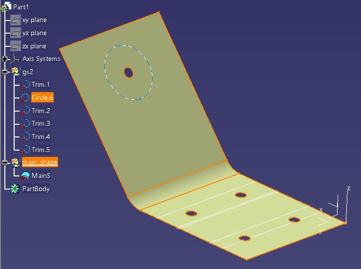
For now the .stp file referenced in CompoST under CompositeStandard.FileMetadata() is the reference surface that the splines should be projected on. The .stp file should be displaying one
main surface on default. For CATIA automation purposes the “main_shape” geometrical set contains the surface to be projected on.
Active object
Most objects contain active property. This is used for cases when data needs to be kept, but is superceeded. For example, if wrinkle has been identified in a scan, the detail of the wrinkle is stored. However, user might then
implement a process for removing that wrinkle, either eradicating it or replacing it by wrinkle with new data. In this case the property active will be switched from ‘True’ to ‘False’. When this property is not used, user should
assume the object is active. This needs to be kept in mind in processes where some objects might be de-activated, as any furhter processing/analysis will need to exclude based on this property/tag.
Stages
Stages help with tracking information sources, allowing for history of changes to the part. Each object can have reference so stages (Stage object) to indicate when and how was this object edited.
On default if Stage is not assigned to an object it should be assumed this object was last edited during the component design stage.
Stages should all be stored in allStages list for iteration. When new stage is created the StageID should be selected to be +1 to the highest number currently listed.
There are two suggested workflows for working with stages. First option is to pre-define all stages at design, assuming the designer knows all the processes that will utilize CompoST in the design, manufacture, and potentially lifecycle of the product. In this case the Stage objects are already all stored, and at each stage new objects are simply created with appropriate ID. For second method the allStages list is left empty at design stage, and each stage is created when the data is being stored. Which option is selected will depend on where in the design process decisions are being made about the product. The first option allows the allStages to also be a workflow definition, with majority of the information being stored in process documents referenced in individual stages. The second option allows for more flexibility.
When an object is invalidated by a new stage, the old object’s active property should be changed to False (it is True on default). The example of this is a Wrinkle found in a ply, that was fixed by subsequent operation. In this case it may be desirable to keep the Wrinkle stored for traceability, to to de-activate the object to indicate it no longer affects the part.
To define Stage the default object Stage can be used, with majority of information being stored in reference documents. However, each stage will likely need bespoke parameters stored, this is what the ‘stageParameters’ dictionary, which is fully defined by user.
Edge of Part
On default all composite objects are defined with the “manufacturing edge of ply”. The ‘EngEdgeofPart’ simulates the final trimming operation, and simply relimits the part according to final trimming operation.
(This logic can still be modified based on real examples and induced limitations)
Tolerances
Tolerances are an important part of CompoST. Howerver, STEP already has a standard for many geometric tolerances. Therefore it is suggested that that standard takes precedence for geometric tolerances. The CompoST tolerances are to be used where the STEP does not have appropriate information to apply tolerances on, specific composite objects. Ultimately it is up to the user, to chose if a specific tolerance is to be defined in STEP or in CompoST. However, the focus here is on tolernaces not covered by STEP, or not covered sufficiently for specific composite applications.
Merging CompoSTs
Ideally CompoST is not to be edited by two actors at the same time, as it should travel with the part, only allowing edits in current process. However, there may be instances when this is not viable. An example is optimisation that requires paralelization, each parallel process editing CompoST file of the same part. This small section outlines guidance on how to merge CompoST files in such niche cases. Note, this is not intended behaviour, but is presented here for those unforseen scenarios.
The suggested steps to merging branched CompoST files is below, but only some steps might be required.
Evaluate the difference
Unless user has a very clear idea of what was added at each stage, this needs to be investigated. For that purpose ‘deepdiff’ Python library is recommended. Similar to below:
from deepdiff import DeepDiff
diff = DeepDiff(base_CompoST,edited_CompoST)

for change_type, changes in diff.items():
        print(f"Change type: {change_type}")
        print(changes)
This will display the type of change that was done to CompoST file and the exact variation. This is only useful for reasonably small changes. For more complex variations (meshes etc…) it will be easier to review the process that causes the changes.
Ignore the most complex of the variations
When merging multiple CompoSTs it is worth identifing the most complicated edit, and then adding the other changes to that.
Test addition of the other CompoSTs
Write small code that adds the changes identified in 1 and add that to the source CompoST (before any branching occured). The edited base-CompoST should then be tested by ‘deepdiff’ and no meaningful variations should exist.
Iteratively add all changes
Use the tested code from 3 to edit CompoST identified in 2.
Careful about the IDs!
The main issue with merging CompoSTs are conflicting IDs. This is very important as with the base .jsen deserialization into Python objects the IDs are used to relink objects.
It is recommended that all objects added in 4 are given new IDs, updating the ‘CompositeDB.fileMetadata.maxID’ with it.
Alternatively, merginig CompoSTs could be done using Git, but author has not tested how practical that is for complex parts/files.